Plunge into PinMode -- Behind the Libraries Part Two
21 October 2018
In the first article of this series, we saw how to can turn pins on or off on an Arduino Uno by directly writing 1s or 0s to specific registers. Today, we'll explore how to change the mode of a pin.
The pinMode function essentially works the same as our replacement for digitalWrite, in that we replace the function call by changing a particular bit in specific memory location. But there is a wrinkle. digitalWrite only had two possible values to set a pin (HIGH or LOW) and therefore one bit of memory was sufficient to cover both options. With pinMode, this isn't the case, as it allows us to set three different modes: INPUT, OUTPUT, and INPUT_PULLUP. We need at least two bits.
Four Modes?
But when considering how the ATmega328p chip works, even though pinMode only acknowledges three modes, it is easier to consider there to be there to be four modes: INPUT, INPUT_PULLUP, OUTPUT LOW, and OUTPUT HIGH.
We saw in the previous article how changing the 5th bit of the PORTB register, located at 0x25, turns pin 13 (when it is set to be an output pin) on or off. As it turns out, if we alternatively set pin 13 to be an input pin, this bit would determine whether the pin is INPUT (off) or INPUT_PULLUP (on). So all we need to know is how the other bit that determines the mode, which is found in data direction register B (DDRB). Referring to the ATmega328p datasheet and Arduino Uno schematic, we learn that for pin 13 we need to set the 5th bit of data direction register B (DDRB) at address 0x24.
| DDRB (0x24) 5th Bit | PORTB (0x25) 5th bit | Pin 13 Mode |
|---|---|---|
| 0 | 0 | INPUT |
| 0 | 1 | INPUT PULLUP |
| 1 | 0 | OUTPUT LOW |
| 1 | 1 | OUTPUT HIGH |
We can use this information to take out pinMode from our program using the same bitwise operators we used in the previous article:
void setup() {
*(uint8_t *)0x24 |= 0b00100000;
}
void loop() {
*(uint8_t *)0x25 |= 0b00100000;
delay(1000);
*(uint8_t *)0x25 &= 0b11011111;
delay(1000);
}
At this point, you might say to yourself, "I am wasting my time learning about this stuff". And unfortunately, in this particular case, you're right. By default, after booting up, all pins on the Arduino are set to output pins, so don't even need to set the 5th bit of the DDRB register.
void setup() {
}
void loop() {
*(uint8_t *)0x25 |= 0b00100000;
delay(1000);
*(uint8_t *)0x25 &= 0b11011111;
delay(1000);
}
Switching Modes and the Pull-Up Disable Bit
According to the datasheet (p99), there is a potential problem that can occur when switching modes from INPUT (so the PORT bit and DDRB bits are 0b00) to OUTPUT HIGH (0b11) or from OUTPUT LOW (0b10) to INPUT PULLUP (0b01), which is that you cannot change between these states instanteously as you must flip two bits, requiring two separate instructions. So after issuing the first instruction, you would temporarily be in a mode you don't want to be in, which in rare cases can cause problems.
I bring this up not because it is something that should concern us, but because the solution offered to this problem is the pull-up disable bit (PUD). This is worth mentioning because the PUD bit can overrule the changes you've made to the DDR and PORT registers. The PUD bit is off by default, but if you turn it on, even if all pins are set to be input pullup, they become input pins. This bit allows you to jump straight from OUTPUT HIGH to INPUT. The PUD bit is the 4th bit in the microcontroller control register (MCUCR) at address 0x55.
| DDR bit | PORT bit | PUD bit | Pin Status |
|---|---|---|---|
| 0 | 0 | N/A | INPUT |
| 0 | 1 | 0 | INPUT PULLUP |
| 0 | 1 | 1 | INPUT |
| 1 | 0 | N/A | OUTPUT LOW |
| 1 | 1 | N/A | OUTPUT HIGH |
Reading from Pins
As the DDR and PORT registers controlled the mode and output of the Arduino's pins, whether a pin is currently HIGH or LOW is recorded in the PIN registers. The bits in the PIN registers automatically change depending on whether a high or low voltage is applied to the corresponding pin.
We're going to be reading the value of pin 12. To help us do this, I've created a simple circuit so we can turn pin 12 on or off using a button.
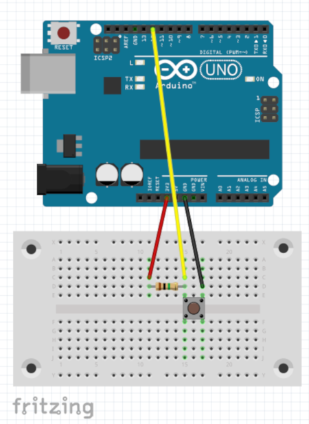
I've used an 100k resistor. Pin 12 will be HIGH when the button isn't pressed, and LOW when it is.
The 4th bit of the PINB register is found at location 0x23. The bit is 1 if pin 12 is HIGH, and 0 if pin 12 is LOW. I can use this to write a program that turns the Uno's on-board LED on when the button is pressed.
void setup() {
pinMode(12, INPUT);
pinMode(13, OUTPUT); // to control on-board LED
}
void loop() {
// result == 0 if 4th bit is 0, result == 16 if
// 4th bit is 1 (since 0b10000 == 16)
int result = *(uint8_t *)0x23 & 0b00010000;
if(result == 0)
digitalWrite(13, HIGH);
else
digitalWrite(13, LOW);
delay(10);
}
Read and Write from Any Pin
Here is a handy table to show how the location of the bits that control the mode of any GPIO pin on the Arduino. I've grouped together the PIN, DDR, and PORT registers, as the pins are controlled by the same bits.
PINB 0x23 / DDRB 0x24 / PORTB 0x25
| Bit | 7 | 6 | 5 | 4 | 3 | 2 | 1 | 0 |
| Pin | X | X | 13 | 12 | 11 | 10 | 9 | 8 |
PINC 0x26 / DDRC 0x27 / PORTC 0x28
| Bit | 7 | 6 | 5 | 4 | 3 | 2 | 1 | 0 |
| Pin | X | RESET | A5 | A4 | A3 | A2 | A1 | A0 |
PIND 0x29 / DDRD 0x2A / PORTD 0x2B
| Bit | 7 | 6 | 5 | 4 | 3 | 2 | 1 | 0 |
| Pin | 7 | 6 | 5 | 4 | 3 | 2 | 1 | 0 |