Diving into DigitalWrite -- Behind the Libraries Part One
20 October 2018
void setup() {
pinMode(13, OUTPUT);
}
void loop() {
digitalWrite(13, HIGH);
delay(1000);
digitalWrite(13, LOW);
delay(1000);
}
How does this code make the Arduino Uno’s on-board LED (or an LED connected to pin 13) blink? That was the question I was asking myself after getting the program to work. I was wondering what functions like pinMode and digitalWrite did, how the underlying hardware worked. In this series, that's what I intend to find out.
The goal of the series is to gain mastery over the Arduino Uno as a piece of hardware, rather than its associated tools and libraries. Sometimes the Arduino libraries and IDE can make accessing the hardware directly more difficult, but I think the availability and convenience of the Arduino Uno and its associated tools overrule these issues. And hopefully, as the series progresses, we'll discover ways to overcome these difficulties.
I've tried to provide links to further explanation for concepts that I don't explain myself. If I haven't clearly or correctly explained anything, please let me know. I'd welcome any feedback.
Peaking Behind digitalWrite
When we write "digitalWrite(13, HIGH), essentially all the function does is write a "1" into the specific bit of memory that relates to pin 13. When we set the pin to "LOW", it writes a "0". So, if we know the memory address of the bit that determines whether pin 13 is on or off, we can access it directly instead of using the digitalWrite function.
On an Arduino Uno, this bit of memory is located on the ATmega328p chip that is essentially the brains of the Arduino. If you look at the biggest chip on your Arduino, you will see the Atmel logo and MEGA328P written on it. As well as producing the chip, Atmel also produce a datasheet for it. It is an exhaustive guide to everything the chip does. Using it, we can learn the address of bit of memory we're looking for.
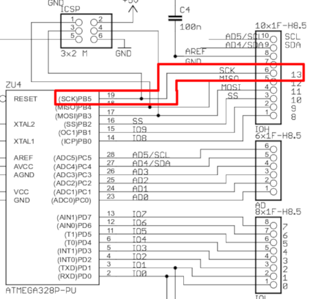
By looking at the Arduino's schematics, we can discover that pin 13 is connected to the PB5 pin (or PORTB5) of the ATmega328p chip.
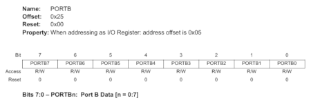
The datasheet (p116) tells us that the bit that controls the output of that pin is found at the address 0x25. That hexidecimal address points to an 8-bit register, which is essentially a piece of memory that can store eight bits, eight 1’s and 0’s. According to the datasheet, the 5th bit stored in the register at address 0x25 controls whether pin 13 is on or off.
NOTE: While a standard PC contains only one memory space, the ATmega328p actually contains three separate memory spaces. This introduces ambiguity, as the address 0x25 can refer to multiple pieces of memory. If we try to access address 0x25 in C, however, the compiler gives us access to SRAM, which is what we want.
We can see from the datasheet how the eight bits of the register are numbered, with the 0th bit being the least significant, and the 7th being the final and most significant.
Unfortunately, if we want to avoid all library use, the following jiggery pokery is necessary to access this register in our code:
*(uint8_t *)0x25
The "(uint8_t *)" casts the hexidecimal value 0x25 as an unsigned 8-bit integer that points to something (i.e. we're saying it is an address). Once we’ve established that 0x25 is an address, the sole "*" before it asks the program to give us access to the memory located at that address -- known as dereferencing a pointer.
NOTE: There is a more readable way to access registers like this by using predesignated labels defined for us. In this case, rather than "*(uint8_t *)0x25", we could have simply wrote "PORTB".
Now we have access to the 8-bit register and we can change the values of those bits. In C, we can do this with bitwise operators, specifically the & and |, relating to logical AND and OR respectively.
The bitwise operations in C page on Wikipedia explains how they work, but the jist is that we can use | to set bits to 1 and & to set bits to 0.
*(uint8_t *)0x25 |= 0b00100000;
This sets the 5th bit of the register at address 0x25 to 1, while not changing the other bits. ("A |= B" is equivalent to "A = A | B".)
*(uint8_t *)0x25 &= 0b11011111;
This sets the 5th bit of the register at address 0x25 to 0, while not changing the other bits.
Because we know the 5th bit in that particular register controls whether pin 13 is on or off, we can use these lines of code and remove digitalWrite from the default blink program.
void setup() {
pinMode(13, OUTPUT);
}
void loop() {
*(uint8_t *)0x25 |= 0b00100000;
delay(1000);
*(uint8_t *)0x25 &= 0b11011111;
delay(1000);
}
If you load this code on to your Arduino, it will work like the default blink program found in File -> Examples -> 01.Basics.
NOTE: We could instead have used "PORTB |= (1 << PORTB5);" and "PORTB &= ~(1 << PORTB5);".
Turning Other Pins On/Off
Other pins can be turned on or off in the same way. The information to do so can again be found using the datasheet and the Arduino schematics. Below is the relevant information to save you the search:
| Bit | 0x25 | 0x28 | 0x2B |
|---|---|---|---|
| 7 | X | X | 7 |
| 6 | X | RESET | 6 |
| 5 | 13 | A5 | 5 |
| 4 | 12 | A4 | 4 |
| 3 | 11 | A3 | 3 |
| 2 | 10 | A2 | 2 |
| 1 | 9 | A1 | 1 |
| 0 | 8 | A0 | 0 |
Using this information you can turn any pin on or off. For example, to turn pin 0 on you would write:
*(uint8_t *)0x2B |= 0b00000001;
Next time we’ll explore how the pinMode function works.
Sources:
Robert Paz's Arduino Basics Lectures
GarretLab's Playing with Arduino Webpage