Shuffling into Serial -- Behind the Libraries Part Five
21 October 2018
We're slowly understanding various parts of the Arduino Uno and, more specifically, the ATmega328p chip. Next on the agenda are the various Serial commands we used, such as Serial.begin and Serial.print.
Before we learn how to do serial communication without using the Arduino libraries, firstly we need to learn how functions like Serial.println work behind the scenes.
What is USART/Serial?
USART is hardware that allows two or more devices to communicate. In this instance, we're interested in one particular mode of the USART called asynchronous mode. This mode uses two wires to allow communication between two devices. One wire is used to receive data and the other to send data. Pins 0 and 1 on the Arduino Uno, which receive (RX) and transmit (TX) respectively, are used for this type of communication. Also for convenience the Arduino has a Serial-to-USB chip, separate from the ATmega328p, which converts serial data communicated over pin 0 and 1 into something that can be transmitted over USB, which is what allows the Arduino to connect to a computer and use the Arduino IDE.
How can two devices communicate?
Just as two people speaking must use the same language to communicate, two devices, to communicate data over one wire (or more), need to use the same protocol.
The protocol dictates how the communication occurs. On a single wire, we only have two options, on and off. So the communication depends on how we structure those periods of being on or off such that data can be communicated.
Let's look at an example. We might keep a wire HIGH permanently when communication isn't occuring. If we want to start transmitting data, we bring it LOW for one second to indicate to the receiver that communication is about to begin. Then we set the wire HIGH or LOW depending on what the particular bit we want to transmit is, and leave it at that for a second, and then repeat that until we've transmitted 8 bits after 8 seconds. Finally, after the data has been transmitted, we go HIGH to indicate the transmission has finished and either stay HIGH or go LOW again to transmit another byte of data.
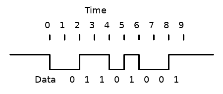
With this method, we have transmitted 8 bits in a "frame".
NOTE: The least signficant bit is often sent first, so my example wouldn't have transmitted the number 0b01101001, but that number backwards, 0b10010110.
It is important that the sender sets the wire HIGH or LOW at a different time to when the receiver reads the wire. In the above example, at precisely two seconds the sender set the wire to HIGH. Ideally, the receiver would read the wire at 2.5 seconds. If the receiver reads data from the wire at the same time, it is possible it will grab the wrong value.
One way some protocols achieve this is by having a separate "clock" wire. A clock wire operates like the Arduino Uno's crystal oscillator, in that it toggles on and off at a set frequency.
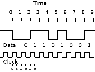
In the above example, the sender writes (W) the next value to the wire each time the clock wire rises, and the receiver reads (R) each time the clock falls. If both sender and receiver can see the clock wire, then it makes it trivial to avoid writing and reading from the data wire at the same time.
No clock wire
USART uses no clock wire that both devices can see. This saves the need for a third wire, but adds the problem of synchronising the two devices. The way this synchronisation is achieved is through both devices having their own internal clock, and both being set to the same rate.
This is why the Serial.begin command is needed and why the Arduino IDE's Serial Monitor prints gibberish if you set the wrong rate. In my example above that didn't include a clock wire, the communication only occurs if both devices read/write every second. If the device receiving data instead read every 1.5 seconds, for example, then the sender's data wouldn't be recieved.
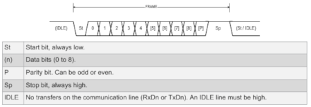
This is taken from p223 of the ATmega328p datasheet, showing how USART sends bits. USART can send a different number of bits each frame, but in the above example, it sends nine bits (0 to 8). At the end of the frame, it can either idle or immediately send another frame.
You'll notice it works almost the same as my example of how eight bits could be sent. The one difference is the addition of the parity bit. This isn't something we'll be using in this article, but it is used to help check whether the data bits were sent correctly -- it tells the recepient whether the intended transmission is even or odd.
Example Code
Now that we've explored how Serial works behind the scenes, we can now learn how to use USART directly. Here is an example program that repeatedly sends the character 'A' using the USART:
void setup() {
//Baudrate to 9600
UCSR0A &= 0b11111101;
UBRR0 = 103;
// Use 8 data bits, UCSZ2:0 = 0b011
UCSR0B &= 0b11111011; // UCSZ2 = 0
UCSR0C |= 0b00000110; // UCSZ1:0 = 0b11
// Enable transmission
UCSR0B |= 0b00001000; // TXEN0 = 1;}
void loop() {
// Wait until ready for new data, i.e. UDRE0 bit == 1
while( (UCSR0A & 0b00100000) == 0);
UDR0 = 65;}
Before we breakdown this program, let's cover what registers we are using.
UCSR0A/B/C are three USART Control and Status Registers. They allow us to configure the USART mode, whether transmitting and receiving are enabled, the number of data bits, whether we use a parity bit, and so on. They also give us information, such as whether it's ready for new data or whether it has transmitted the data it was previously given.
UBRR0 is a 16-bit value contained in two registers UBRR0L and UBRR0H, like we saw with TCNT1. The value it contains controls the baudrate.
UDR0 is used to both hold the data we want to send and read any data we've been sent. Behind the scenes, this label actually refers to two different 8-bit registers, but which we access depends on whether we read or write to that label. If we set UDR0 to a value, then we're setting the USART Transmit Data Buffer Register. If we read from UDR0, we're reading from the USART Receive Data Buffer Register.
NOTE: In the above program, there are some configuration options that we're not setting because they're already set as we want by default. For example, the USART is by default set to asynchronous mode. This article isn't intended to be an indepth guide to everything about USART. If you're interested in going deeper into what these options are, the datasheet has the answers.
UCSR0A &= 0b11111101
UBRR0 = 103;
This configures the baudrate to 9600. What to set this value to would be confusing, with us having to crunch numbers into a formula from the datasheet, but thankfully the datasheet also contains a large table of common clock rates and the value to use for particular baudrates on p241. As we discovered in a previous article, the Arduino Uno runs the 328p at 16Mhz, so all we need to do is look at the relevant section of the table and use those values.
UCSR0B &= 0b11111011; // UCSZ2 = 0
UCSR0C |= 0b00000110; // UCSZ1:0 = 0b11
This sets the three bits that determine the number of data bits. Like in previous cases, it's unclear why these three bits are spread across two registers -- presumably a hardware design reason.
while( (UCSR0A & 0b00100000) == 0);
Here we loop continuously until the UDRE0 bit is 1. This bit is automatically set to 1 when the USART is ready for the new data.
UDR0 = 65;
Serial Monitor uses ASCII, which basically translates the 8-bit value we send into its associated character. In this instance, 65 relates to the character 'A'. You can see which values relate to which characters by looking in the ASCII table.
Screw USART. Let's Bit Bang
Since this series is about understanding how things work on a hardware level, we can use everything we've learned in this article to transmit data without using USART and instead using digitalWrite and delayMicroseconds. We can do with software what USART did with hardware.
If we want to communicate at 9600 baud, that is 9600 bits per second or 1 / 9600 = 0.000104166666666667 seconds per bits or approximately 104 microseconds. We also know that pin 1 is what Serial uses to transmit data. Using this information, we can write our program:
void setup() {
pinMode(1, OUTPUT);
digitalWrite(1, HIGH); // Start HIGH to indicate no transmission occurring
}
void loop() {
delayMicroseconds(104); // 104 microsecond delay for 9600 baud
digitalWrite(1, LOW); // start bit
// 'A' == 65 == 0b01000001
// Least significant bit first
delayMicroseconds(104);
digitalWrite(1, HIGH); // 1
delayMicroseconds(104);
digitalWrite(1, LOW); // 0
delayMicroseconds(104);
digitalWrite(1, LOW); // 0
delayMicroseconds(104);
digitalWrite(1, LOW); // 0
delayMicroseconds(104);
digitalWrite(1, LOW); // 0
delayMicroseconds(104);
digitalWrite(1, LOW); // 0
delayMicroseconds(104);
digitalWrite(1, HIGH); // 1
delayMicroseconds(104);
digitalWrite(1, LOW); // 0
delayMicroseconds(104);
digitalWrite(1, HIGH); // stop bit
}
This should repeatedly print 'A' to the Serial Monitor. To prove this isn't a fluke, you can change the transmitted data to print other characters. For example, if you change the HIGHs and LOWs so it transmits 66 or 0b01000010, it will print 'B' repeatedly.
End of the series?
I originally intended to go further with this series, but then I got a job as a tester and learning about the ATmega328p was no longer my priority. So while I've put these posts up, and it was fun to work this stuff out, you can consider this the end of Behind the Libraries.