Delving into Delay -- Behind the Libraries Part Three
21 October 2018
So far in this series, we've been methodically producing workarounds for library functions, sidestepping digitalWrite and digitalRead and pinMode. But as we've done this we've been using the delay function. The reason I've ignored this is because implementing delay is much more complicated.
But now that we understand the basics of how to interact with the hardware of the Arduino Uno -- how to read and write to registers -- we can start to explore some of its more complicated features.
The delay function depends on two different features of the ATmega328p: timers and interrupts. We'll be exploring one at a time, starting with timers, as we work towards our own alternative version of delay.
What are timers?
The simplest timer counts from zero to the max value it can hold and then overflow to zero. So a 2-bit timer, for example, would count 00, 01, 10, 11, then overflow back to 00.
On the Arduino, the timers on the ATmega328p chip count up in line with a crystal oscillator. You can see this on the Arduino with the number "16.000" etched on it. This indicates that it pulses at 16Mhz, or 16,000,000 times a second.
The Ardunio Uno's ATmega328p chip has three timers, timer0, timer1, and timer2. Timer0 and timer2 are 8-bit timers, and timer1 is 16-bits. This means that timer0/2 can count up to max of 255, while timer1 can count to 65535. Each of these timers count in step with the crystal oscillator, so by default they are incremented 16 million times a second.
For our alternate delay function, we'll be using timer1 -- timer0 is already being used by the Arduino's delay function and the extra range of 16-bits makes it easier to watch the count sequentially increase.
Timer1's 16-bit counter, TCNT1, is found at address 0x84. We can access it like so:
void setup() {
Serial.begin(19200); // Remember Serial Monitor must also be set to 19200
}
void loop() {
Serial.println((uint16_t )0x84);
}
NOTE: TCNT1 is actually two 8-bit registers, TCNT1L and TCNT1H (low and high bytes respectively). These two registers are used together as one 16-bit value. So when we ask for a uint16_t from address 0x84, behind the scenes our program is separately grabbing the values from 0x84 and 0x85.
On running this program, you'll notice that it doesn't work as expected. We might expect 16-bit timer to count up to 65535 (when all 16 bits are 1), but it only counts up to 255.
You'll also notice that it doesn't count sequentially. This is because the timer is counting too fast for our program to keep up. It takes many ticks of the crystal oscillator to perform the Serial.println function, and so in the time it takes for Serial.println to print one value to the Arduino IDE's Serial Monitor, timer1 has already overflowed.
Both of these problems can be solved by changing configuration options for the timer. All three timers on the ATmega328p offer many options, depending on how you want to use them, which can be changed by alternating the bits of their associated control registers. The particular "waveform generation" mode used by timer1 is set in two control registers, TCCR1A and TCCR1B. You can see the modes listed on p171-2 of the ATmega328p datasheet.
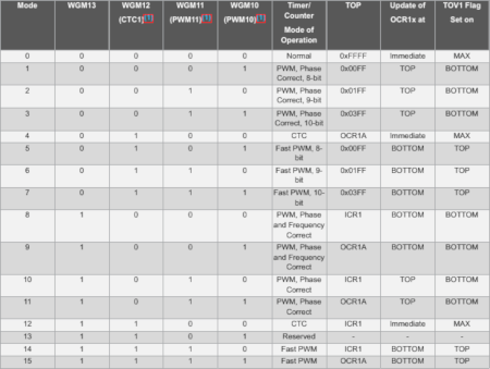
By default timer1 is set (amongst other things) to mode 1, which only allows it to count up to 255 -- as indicated in hexidecimal in the "TOP" column. This is because the Arduino sets up timer1 and timer2 for use with the analogWrite function. By altering this to mode 0, it will then count to 0xFFFF or 65535. This can be done by setting the four waveform generation bits -- WGM10 to WGM13 -- all to zero. These bits are confusing located in two different locations. WGM10 and WGM11 are the 0th and 1st bits of TCCR1A (0x80) and WGM12 and WGM13 are the 3rd and 4th bits of TCCR1B (0x81).
void setup() {
Serial.begin(19200); // Remember Serial Monitor must also be set to 19200
*(uint8_t *)0x80 &= 0b11111100;
*(uint8_t *)0x81 &= 0b11100111;
}
void loop() {
Serial.println(*(uint16_t *)0x84);
}
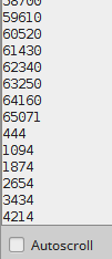
You should now see in the Arduino IDE's Serial Monitor (if you disable autoscroll) the value of timer1 increase to 65535 before overflowing and counting up from zero again.
You'll also notice that the counter is increasing almost 1000 times in the time its takes our program to print its value. This is because serial communication is slow compared to our timer!
Changing the Speed of the Timer
From what we've seen so far, we can see how fast timers on the Arduino count, and how it has many different configuration options. This fast and precise counting can be used for many applications, like using PWM to change the brightness of an LED or to play a particular note through a speaker. But we are looking to recreate the delay function, which means we want to measure longer time periods.
One configuration option the Arduino's timers offer us is to slow down the speed of the counting using a prescaler. For timer1, instead of having it count 16 million time a second, we can also set it to count 8, 64, 256, or 1024 times slower. By default timer1 on the Arduino is set to count 16,000,000 / 64 times a second, or at 250,000Hz.
We can change to the particular prescaler value we want using the clock select bits found in the 0-2 bits of the TCCR1B register. We can see what the various options do in the ATmega328p datasheet p173-4:
| Bit 2 | Bit 1 | Bit 0 | Description |
|---|---|---|---|
| 0 | 0 | 0 | Stop counter |
| 0 | 0 | 1 | No prescaler (so counts at 16Mhz) |
| 0 | 1 | 0 | Clock / 8 |
| 0 | 1 | 1 | Clock / 64 |
| 1 | 0 | 0 | Clock / 256 |
| 1 | 0 | 1 | Clock / 1024 |
| 1 | 1 | 0 | Count using pin 5 as input, every time it goes from 1 to 0? |
| 1 | 1 | 1 | Count using pin 5 as input, every time it goes from 0 to 1? |
We can show how using (or not using) a prescaler can speed up or slow down timer1:
void setup() {
Serial.begin(19200); // Remember Serial Monitor must also be set to 19200
// Setting waveform generation mode 0
*(uint8_t *)0x80 &= 0b11111100;
*(uint8_t *)0x81 &= 0b11100111;
// Setting no prescaler
*(uint8_t *)0x81 &= 0b11111001;
*(uint8_t *)0x81 |= 0b00000001;
// Setting / 1024 prescaler
//*(uint8_t *)0x81 &= 0b11111101;
//*(uint8_t *)0x81 |= 0b00000101;
}
void loop() {
Serial.println((uint16_t )0x84);
}
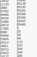
You can uncomment or comment the no prescaler and 1024 prescaler settings and watch how it speeds up or slows down the counter. You'll find that with no prescaler it should overflow 16,000,000 / 65536 = 244 times a second, which is too fast for Serial.println to keep up. It won't appear to count sequentially as the counter is counting more than 65535 times in the time it takes to print to Serial Monitor. With 1024 prescaler, Serial.println will be able to keep up and more clearly show the timer1's count registers counting up to 65535 before overflowing.
Timing Even Longer Periods
Even though using prescalers slows down the timer, many projects require the ability to wait for minutes, hours, days, or even weeks. This isn't possible even the timer1's 16 bits while using its highest prescaler.
But there is a solution: to introduce another variable to count the counter. This is perhaps easiest to demonstrate as a program that blinks an LED:
void setup() {
pinMode(13, OUTPUT);
// Setting waveform generation mode 0
*(uint8_t *)0x80 &= 0b11111100;
*(uint8_t *)0x81 &= 0b11100111;
// Setting / 1024 prescaler
*(uint8_t *)0x81 &= 0b11111101;
*(uint8_t *)0x81 |= 0b00000101;
}
int count = 0;
void loop() {
if((uint16_t )0x84 > 16000) {
count++;
*(uint16_t *)0x84 = 0;
if(count >= 10) {
digitalWrite(13, !digitalRead(13));
count = 0;
}
}
Given what we know, we can work out how often the Arduino's on-board LED should toggle. Count should be incremented every 16Mhz / 1024/ 16000 times a second. We're toggling the on-board LED every time count gets to 10, so it should toggle every 16000000 / 1024 / 16000 / 10 times a second or 0.01 times a second, or once every 10 seconds.
This imprecision is a problem we'll solve next time, when we introduce interrupts.
But there is a slight problem here. If timer1 was reset to 0 precisely when it reached 16000, and the LED was toggled at the exact moment it overflowed for the tenth time, then it would be precisely ten seconds between each toggle. But timer1 is actually being allowed to count over 16000 before we reset it (so it might reach 16100, for example) and so it will take longer than 10 seconds before we toggle the LED.